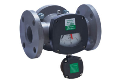
Compact flowmeter for water, oil, and various liquids.
Flaptor® series
Flexible selection of flow direction.
Either vertical or horizontal direction is available. Designate the flow direction on ordering.
Small space is enough for installation.
No need of straight pipe right before Flaptor.
Application to flow switch
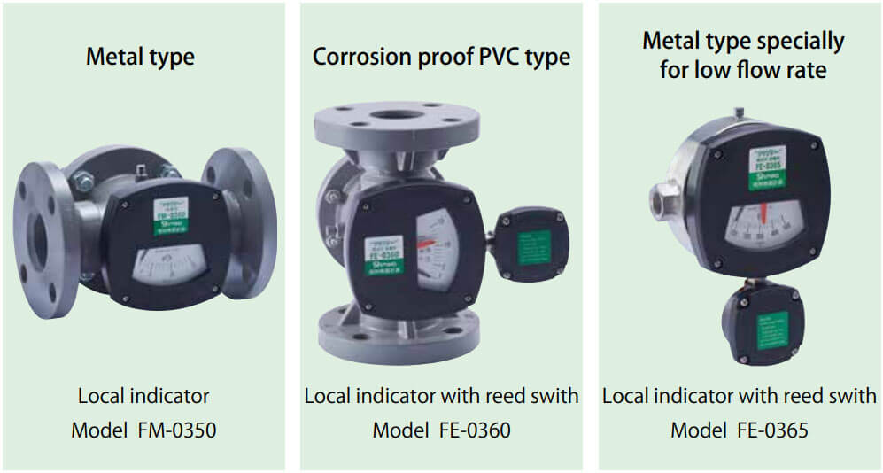
Model FE-0360 has a reed switch with long lifetime.
Easy maintenance.
When cleaning the Flaptor inside, just taking the cover flange out, not necessary to take the Flaptor body out from piping.
High durability.
Simple structure and all metal body.

Local indicator with reed switch FE-0360

Please select the models shown above according to customer demand.

Flow direction(Please specify the flow direction on ordering.)
Operation principal

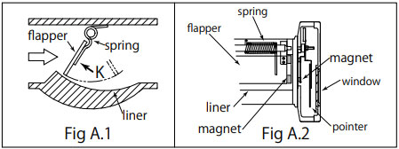
Figure A.1 shows the schematic cross-section of Flaptor body. The measurement principle of Flaptor is basically the same as that of variable area flowmeter.
When liquid/gas flow hits the flapper, the flapper rotates towards downstream due to the differential pressure, as the pressure in the upstream side is higher than that of the downstream.
The flapper simultaneously receives the force of the spring placed in the hinge so that it rotates towards the upstream. Thus, the flapper is stabilized at the position where the difference pressure force is in balance with the spring force.
As shown in Fig. A.2, the flapper magnetically couples with the pointer in the indicator portion which is placed outside of the body. The flapper angle varies depending on the amount of fluid passing through the space between the flapper and the liner. As the liner is specially designed, the flapper angle and the pointer angle vary proportionally to the flow rate. The mechanism achieves the indicator where the scale spacing of scale plate is almost equal.
Catalog download

If you have any questions, please feel free to contact us.
Showa Instrument Information Co.,Ltd.
Sales : 6-4-17 Higashi-Koujiya, Otaku, Tokyo, Japan
TEL +81 03-6756-0601 FAX +81 03-6756-0602
Head office・Factory : 6-4-17 Higashi-Koujiya, Otaku, Tokyo, Japan
TEL +81 03-3745-3361 FAX +81 03-3745-3395
